This guide explains how the Extech EX900 can support professional AC/DC current measurement, voltage testing, troubleshooting, and maintenance work. The instrument belongs to the clamp-meter category, using a hinged jaw to measure current without disconnecting a conductor. Its suitability depends on the exact model specification, measurement category, conductor size, environment, and the user’s procedures. Always confirm the current datasheet, manual, safety markings, and calibration status before relying on readings.
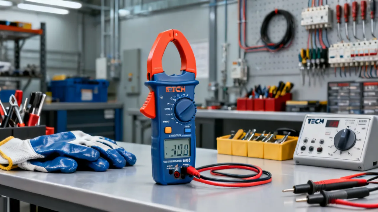
The Extech EX900 is a professional electrical test instrument intended for measuring current through a conductor without requiring the conductor to be opened, disconnected, or placed in series with the meter. This basic clamp-meter function is especially valuable in service work, industrial maintenance, building systems, motor diagnostics, commissioning, and field troubleshooting, where interrupting a circuit may be inconvenient, disruptive, or unsafe.
Unlike a conventional multimeter, which generally measures current by placing the instrument in series with a circuit, a clamp meter surrounds one conductor with a jaw. The meter senses the magnetic field associated with the current and presents a reading on its display. This method reduces circuit disruption and allows technicians to investigate energized equipment more efficiently, provided that the instrument is used within its stated electrical and environmental limits.
The EX900 is commonly associated with True RMS AC/DC clamp-meter applications. In practical terms, that means it is intended to provide more useful readings on many non-sinusoidal alternating-current waveforms than an average-responding meter. Modern electrical systems frequently include variable-frequency drives, switched-mode power supplies, LED drivers, battery chargers, computers, inverters, and other electronic loads. These devices can produce waveforms that differ significantly from a smooth sine wave, making meter selection important.
However, the name of a meter alone should never be treated as a complete technical specification. Users should verify the exact EX900 revision, included accessories, measurement ranges, accuracy tables, safety category, jaw opening, environmental limits, battery requirements, and operating instructions in the current Extech documentation. Product specifications can vary by market, production revision, or distributor listing.
Electrical maintenance often involves a practical tension between obtaining a useful measurement and avoiding unnecessary disturbance to the system. A current measurement taken by opening a circuit can introduce additional exposure to energized conductors, create an opportunity for wiring errors, and interrupt equipment operation. A clamp meter can reduce some of these concerns because the technician can measure around an individual conductor while the circuit remains assembled.
The benefit is particularly clear in several common situations:
These applications do not make the instrument a substitute for safe isolation procedures. A clamp meter helps collect information; it does not remove the electrical hazards associated with arc flash, shock, short circuits, stored energy, or unexpected equipment movement. A technically sound measurement begins with risk assessment, suitable personal protective equipment, and a clear understanding of the installation.
Clamp measurement is also useful because it can preserve the operating condition being investigated. If a machine stops whenever its circuit is opened, a series-connected current test may not reproduce the original problem. A clamp meter allows the technician to observe the circuit while the machine remains connected, which can be important when diagnosing intermittent faults, temperature-related behavior, or loads controlled by an automation system.
From an industry perspective, the important question is not whether the Extech EX900 has an impressive list of functions. The better question is whether its capabilities correspond to the measurements a technician actually needs. Several features deserve close attention before purchase or deployment.
Many clamp meters are designed primarily for alternating current. A model that also measures direct current is more versatile because it can support automotive, battery, renewable-energy, controls, telecommunications, and industrial electronics work. Before measuring DC current, the user should understand the meter’s zeroing procedure. Hall-effect clamp sensors can retain a small offset caused by the earth’s magnetic field, nearby conductors, or the position of the jaw. A zero function, when provided, should be used as directed by the manual.
When measuring current, the jaw must generally enclose one conductor only. If both the outgoing and returning conductors pass through the jaw together, their magnetic fields may largely cancel, producing a low or misleading reading. This is one of the most common sources of error in clamp-meter work.
AC and DC current measurements should also be distinguished during troubleshooting. A motor supplied from a conventional AC source, for example, may be evaluated with the AC current function, while a battery bank, charging cable, or photovoltaic conductor may require the DC function. Selecting the wrong current type can result in a zero, an unstable display, or a value that does not represent the actual load.
True RMS measurement is relevant when the waveform is distorted or when loads are controlled electronically. An average-responding AC meter is calibrated to display the correct RMS value for a clean sine wave. On a distorted waveform, that approach can produce a reading that differs materially from the heating-equivalent current.
True RMS technology generally gives a more appropriate result for many real-world loads, but it does not make every reading automatically accurate. The crest factor, bandwidth, measurement range, conductor position, and waveform characteristics still matter. A meter may also have different accuracy specifications for low-level measurements, high-frequency signals, or readings taken near the ends of a range.
For example, a switching power supply may draw current in short pulses near the peaks of the voltage waveform. An average-responding meter can interpret this current differently from a True RMS meter. Even with True RMS measurement, a technician should check whether the waveform falls within the instrument’s specified frequency and crest-factor limits. If the application requires harmonic analysis or waveform recording, a power-quality analyzer may be more suitable.
A clamp meter is often used as a general-purpose multimeter. Depending on the confirmed EX900 specification, users may have access to AC and DC voltage, resistance, continuity, diode, capacitance, frequency, or related functions. These features can be useful for diagnosing open circuits, checking control signals, verifying supply voltage, and examining passive components.
Users should distinguish between a function being displayed on a marketing page and the conditions under which that function is specified. For example, voltage accuracy can vary by frequency and range. Resistance measurements can be affected by parallel circuits. Capacitance measurements can be influenced by components that remain connected to the circuit. Frequency readings require an adequate signal level and may not be meaningful on a noisy or unstable waveform.
Resistance and continuity testing require particular care. The circuit must be de-energized, and capacitors or other stored-energy components must be discharged through an appropriate procedure before the test leads are connected. A resistance reading taken on an energized circuit can damage the meter and create a hazardous situation. A continuity beep indicates a relatively low-resistance path under the meter’s test conditions; it does not prove that the conductor is suitable for carrying its intended load.
Motors, transformers, compressors, lamps, and power supplies can draw a brief current surge when energized. A meter with an inrush function can help capture this event, but the result depends on the instrument’s sampling method and time window. Inrush readings should be treated as diagnostic measurements rather than absolute descriptions of every transient event.
Correct test preparation matters. The technician must position the clamp around the correct conductor, select the relevant function before energization when required, and understand whether the meter records a peak value, an averaged value, or a defined measurement over a particular interval. If the current surge is shorter than the meter’s response window, the displayed value may not represent the actual peak.
Inrush should be compared with the equipment manufacturer’s data and with the protective device’s time-current characteristics. A high starting current may be normal for a motor, while a progressively increasing inrush may indicate mechanical loading, bearing deterioration, low supply voltage, or a failing electronic power supply. Repeating the measurement under similar conditions is more useful than relying on one unverified peak reading.
Variable-frequency drives create measurement challenges because their outputs are not ordinary utility sine waves. A meter may display voltage or frequency values that require interpretation, particularly when pulse-width modulation is present. A low-pass filter or drive-compatible measurement mode, if included in the relevant EX900 configuration, can help reduce the influence of high-frequency switching components. It should not be assumed that a filtered measurement is equivalent to the motor’s complete electrical waveform.
Technicians working around drives should follow the drive manufacturer’s instructions and use instruments specifically suitable for the stated environment. A voltage reading at the drive output may not be directly comparable with a supply-side reading. The measurement objective should be defined first: input voltage, fundamental output component, motor terminal condition, current balance, harmonics, or another parameter.
Current measurements on the output side of a drive may still be useful for comparing phases and evaluating load behavior, but the result should be interpreted according to the meter’s bandwidth and True RMS performance. If the drive is reporting a fault, the technician should also review its internal diagnostic information, parameter settings, acceleration time, overload limit, and motor data.
Measurement category markings are among the most important details on any electrical test instrument. Standards in the IEC 61010 family classify electrical environments according to the expected level of transient overvoltage and the installation location. CAT II, CAT III, and CAT IV are not simple quality labels; they describe different application environments when used with the stated voltage rating and appropriate accessories.
In broad terms, CAT II commonly relates to receptacle-connected loads and local appliance circuits. CAT III generally covers distribution-level installations, including fixed wiring, panels, feeders, and building infrastructure. CAT IV is associated with the origin of an installation and outdoor or utility-side environments. The exact interpretation depends on the standard and application.
A meter marked for a particular category must be used with leads, probes, adapters, and accessories that are also appropriate for the intended voltage and category. The lowest-rated component determines the practical safety boundary. Damaged insulation, loose probe tips, contaminated surfaces, incorrect replacement fuses, or unsuitable accessories can undermine the protection implied by the instrument marking.
Before using the Extech EX900, a qualified user should review:
The category marking should be considered together with the working voltage. A CAT III instrument rated for a lower voltage is not automatically suitable for a higher-voltage CAT III installation. Likewise, a category rating does not authorize use in every environment. The user remains responsible for confirming that the complete instrument setup is appropriate for the circuit under examination.
The following workflow is a general technical guide. It does not replace the official Extech manual, site-specific procedures, or training required for energized electrical work.
Decide what needs to be known before touching the installation. Is the objective to determine running current, compare phases, identify a standby load, check a battery circuit, measure voltage, or capture an inrush event? A clearly defined objective helps prevent unnecessary probing and reduces the chance of selecting an inappropriate function.
It is also useful to decide what result would be considered normal. Consult the equipment nameplate, wiring diagram, service manual, design documents, or previous maintenance records. Without a reference point, a reading may appear unusual simply because the load is operating under a different condition.
Examine the case and jaw for cracks, contamination, loose parts, or signs of impact. Inspect the test leads along their full length. The probe insulation should be intact, and the plugs should fit securely into the correct input terminals. Do not use an instrument that shows damage affecting its insulation or controls.
Close the jaw several times without a conductor inside and confirm that it moves smoothly and closes completely. Dirt or damage at the magnetic jaw surfaces can affect the measurement. Check that the display, rotary switch, buttons, and backlight operate normally before approaching energized equipment.
Consider whether the location includes moisture, conductive dust, corrosive substances, confined spaces, high temperature, or a risk of mechanical movement. A clamp meter may be electrically suitable yet unsuitable for the physical environment. For example, a rotating machine, crowded panel, or elevated platform may require additional controls before measurement begins.
Identify moving belts, fans, shafts, linkages, and automatic starting sequences. Maintain a stable stance and avoid leaning across exposed conductors. If the instrument cannot be positioned without compromising clearance or body control, stop and select a different test method or establish additional safeguards.
Choose AC current, DC current, voltage, resistance, or another function before approaching the conductor whenever practical. If manual range selection is available, select a range that is appropriate for the expected value. Auto-ranging can be convenient, but it may take time to settle or display changing values during unstable conditions.
For voltage measurements, connect the leads to the correct terminals and verify that the function selector is not set to resistance or current. For current measurements, make sure the test leads are not inserted into a current input if the intended test is being performed with the clamp jaw. A basic pre-use check can prevent serious operating errors.
When measuring direct current, close the jaw with no conductor inside and use the meter’s zero or relative function if required. The exact procedure varies by model. A failure to zero can create a consistent offset, especially when measuring low current. Zeroing should be repeated if the instrument position changes significantly or if the magnetic environment changes.
Keep the jaw away from high-current conductors while performing the zero operation unless the manual specifies otherwise. Nearby magnetic fields may cause the zero reference to be inaccurate. If the reading remains unexpectedly high after zeroing, investigate the environment and the instrument rather than attempting to compensate mentally for a large unexplained offset.
Place the jaw around one conductor. Centering the conductor can improve repeatability because clamp sensors may have position-dependent accuracy. Keep the jaw fully closed and make sure no insulation, tie, adjacent conductor, or mechanical obstruction prevents proper closure. Never force the jaw into a position that could damage the meter or the installation.
Where several conductors are close together, confirm visually which conductor is enclosed. In a crowded panel, the apparent conductor may not be the conductor being measured. Use the wiring diagram and circuit identification labels, and do not pull or reposition energized conductors merely to make them easier to clamp.
Allow the displayed value to stabilize. Note whether the load is constant, cyclic, pulsed, or affected by another system event. For motor measurements, record both the operating condition and the reading. A number without context is rarely sufficient for diagnosis. If comparing phases, use a consistent procedure and record the same operating state for each phase.
Observe the sign of a DC reading where polarity information is relevant. Watch for overload indications, unexpected range changes, or a display that never settles. These signs may indicate that the measured quantity exceeds the selected range, the waveform is outside the meter’s effective capability, or the circuit is changing during the test.
After the measurement, move the clamp away from the conductor before changing functions when the situation calls for it. If test leads were used, remove the live lead first according to the applicable safety procedure. Turn the instrument off, inspect it again, and store it in a dry, protected location.
Record the readings promptly, especially when testing a machine that may change state. Include the date, equipment identification, measurement location, function, range, operating condition, and any unusual observations. Good records make later comparisons much more meaningful.
The most reliable routine current measurement places the jaw around one insulated conductor. If the wiring arrangement makes this impossible, a qualified technician may use an approved separation point or another method specified by the installation design. Clamping around a complete cable containing both supply and return conductors normally measures the net magnetic field rather than the current in one conductor.
Make sure the jaw closes fully. An incompletely closed jaw changes the magnetic circuit and can produce a reading that is lower or less stable than expected. Centering the conductor is also preferable, particularly when comparing measurements or working near the lower end of the instrument’s range.
Comparing current among phases can reveal imbalance, unequal loading, connection problems, or motor-related issues. The comparison should be made under a stable and representative load. A temporary difference during startup does not necessarily indicate a fault. Also, a current imbalance may originate from supply voltage imbalance, load characteristics, harmonics, wiring, or a mechanical problem. Current readings should therefore be interpreted alongside voltage, equipment condition, and manufacturer limits.
When testing a motor, record the phase sequence and operating state. A motor that is lightly loaded may have readings that differ from nameplate current without indicating a problem. Conversely, a motor that draws near or above its rated current continuously may require attention even if the phases appear balanced. Temperature, ventilation, mechanical loading, and drive parameters should be considered together.
Clamp meters are convenient, but their low-current resolution is generally not equivalent to that of a dedicated precision ammeter. When the conductor carries a small current, environmental magnetic fields and jaw position can become more significant. If the EX900 specification permits a conductor to be looped through the jaw several times, the displayed current may be divided by the number of loops to estimate the actual current. This technique must be consistent with the instrument’s design and safety instructions.
For example, if a conductor passes through the jaw five times and the meter displays 2.0 amperes, the estimated actual current may be approximately 0.4 amperes, assuming the technique is allowed and the signal remains within the relevant range. The number of turns must be counted accurately, and the conductor must not be arranged in a way that creates an unsafe or mechanically stressed installation.
Battery systems can deliver very high fault current even at relatively low nominal voltage. A low-voltage label does not automatically mean low risk. Before measuring, identify the polarity, possible short-circuit paths, stored energy, and isolation points. Avoid allowing the jaw, probe tips, or accessories to bridge terminals. For a DC clamp measurement, zero the instrument and position the jaw around one conductor, not around both positive and negative conductors together.
Battery current may vary substantially depending on charge state, inverter activity, temperature, and connected loads. A reading taken while a battery is idle cannot be compared directly with a reading taken during charging or high-power discharge. Record whether the current is flowing into or out of the battery and, where relevant, use the displayed polarity to support the interpretation.
Inrush testing should be planned before equipment starts. Confirm that the selected function is appropriate, identify the conductor to be clamped, and keep hands and body position clear of moving or energized parts. Record the operating condition, ambient circumstances, and equipment state. A single inrush number should not be used as the sole basis for replacing a motor, breaker, fuse, or transformer.
Repeat the test if the first start was abnormal or if the equipment had been recently running. A warm motor, a partially charged capacitor, or a different mechanical load may produce a different starting current. If a machine is controlled remotely, coordinate with the operator so that the start sequence is understood and unexpected operation does not occur.
Many apparent meter problems are actually technique problems. Understanding the typical causes of error helps users decide whether a result is credible.
| Observed Situation | Likely Cause | Practical Response |
|---|---|---|
| Very low current reading on an operating circuit | The jaw surrounds both outgoing and returning conductors | Clamp around one conductor only and confirm the wiring path |
| Unstable or fluctuating display | Changing load, distorted waveform, electromagnetic interference, or loose jaw closure | Stabilize the load where possible, close the jaw fully, and interpret the waveform context |
| Unexpected DC current value with no apparent load | Clamp offset, nearby magnetic field, or incomplete zeroing | Remove the conductor, close the jaw, and repeat the zero procedure |
| Different readings at different conductor positions | Position sensitivity or incomplete jaw closure | Center the conductor and repeat the measurement consistently |
| Voltage reading that differs from another instrument | Different waveform response, bandwidth, input impedance, range, or calibration | Compare specifications and test both instruments on a known reference |
| Resistance reading that seems too low | Parallel circuit paths or an energized circuit | Isolate the component and verify absence of voltage before resistance testing |
| Inrush value that appears inconsistent | Different starting conditions or a transient shorter than the capture window | Repeat under controlled conditions and consult the instrument’s response specification |
| Reading changes when the technician turns or moves the meter | External magnetic field, especially during DC measurement | Change position, repeat zeroing, and remove nearby magnetic influences where possible |
| Reading is unexpectedly close to zero | Wrong conductor, both conductors enclosed, or the load is not energized | Trace the circuit and verify the equipment operating state before concluding that current is absent |
Accuracy and resolution are related but not identical. Resolution describes the smallest displayed increment. Accuracy describes how close the result is expected to be to the actual value under stated conditions. A display with many digits does not guarantee proportionally high accuracy.
For professional interpretation, read the relevant accuracy statement in full. It may be expressed as a percentage of the reading plus a number of digits. That formula means the error can be proportionally larger at the lower end of a range. Temperature, humidity, frequency, crest factor, battery condition, and conductor position may also affect the result.
Repeatability is another practical consideration. If the same measurement is taken several times under unchanged conditions and the readings remain close, the setup is likely stable. If the values vary significantly, investigate the load, the instrument, the jaw position, and the environment before drawing a conclusion.
Calibration provides confidence that an instrument continues to perform within its specified limits, but calibration does not correct poor technique. Organizations should establish calibration intervals based on usage frequency, risk, environmental exposure, manufacturer recommendations, and quality requirements. A heavily used meter in an industrial environment may require more frequent inspection than a lightly used instrument kept in controlled conditions.
For field diagnosis, trend information can sometimes be more useful than a single highly precise value. If a pump normally draws 8 amperes and gradually begins drawing 10, 11, and 12 amperes under the same operating conditions, that trend may indicate developing mechanical or hydraulic problems. The technician should still verify the result, but consistent historical records can reveal changes before a protective device operates.
Routine care extends the useful life of a clamp meter and helps preserve measurement confidence. Maintenance should be conservative: clean the outside with a suitable cloth, keep the jaw surfaces free of debris, and follow the manual regarding cleaning agents. Do not immerse the instrument unless the manufacturer explicitly permits it.
Battery replacement should be performed with the instrument disconnected from all circuits. Use the specified battery type and observe polarity. A weak battery can cause erratic operation or inaccurate behavior, particularly when additional functions or a backlight are used. If the meter has a replaceable input fuse, use only the specified type and rating. Installing a higher-rated fuse can defeat an important safety feature.
Store the EX900 away from excessive heat, moisture, direct sunlight, corrosive chemicals, and strong magnetic fields. Protect the jaw from impact and avoid placing heavy objects on the instrument. Test leads should be coiled without sharp bends, and damaged leads should be replaced rather than repaired with improvised insulation.
A functional check before important work is good practice. Confirm that the display activates, the selector responds, the jaw operates smoothly, and the meter produces a plausible result on a known circuit or reference source. This check does not replace formal calibration, but it can identify obvious problems before the instrument is taken into a hazardous environment.
The EX900 may be useful in several sectors, but each sector creates different measurement priorities.
In building service, technicians may measure branch-circuit loads, HVAC equipment, pumps, fans, lighting systems, and control panels. Compact dimensions, clear display visibility, low-current responsiveness, and practical jaw access are often more important than specialized laboratory functions. Work near distribution boards also makes category ratings and probe design essential.
Residential and commercial loads may cycle frequently. Refrigerators, heat pumps, air conditioners, water heaters, and variable-speed fans can produce different currents at startup and during normal operation. Measurements should therefore identify the equipment state and, when possible, include observations over a complete operating cycle.
Industrial technicians may need to examine motors, conveyors, contactors, drives, heaters, and control cabinets. Here, waveform behavior, inrush capture, current comparison, ruggedness, and accessibility can influence the instrument choice. A clamp meter supports diagnosis but should be used alongside equipment documentation, insulation testing where appropriate, mechanical inspection, and maintenance history.
Industrial environments may also involve large conductors that cannot be enclosed by a compact jaw. Before arriving at a job, confirm the approximate conductor diameter and the physical space available around it. A flexible current probe or a larger clamp instrument may be necessary if the EX900 jaw cannot close around the conductor without force or unsafe repositioning.
Solar, storage, and backup-power systems include both alternating- and direct-current sections. A meter suitable for one part of the system may not be suitable for every other part. Users should distinguish between array current, battery current, inverter input, inverter output, and fault-current conditions. The voltage category and accessories must match the exact location of the measurement.
Photovoltaic arrays can remain energized whenever illuminated, even when downstream equipment is switched off. Battery systems can maintain hazardous energy after the utility supply is disconnected. Isolation and verification procedures must account for these characteristics. A clamp meter can measure current without opening a conductor, but it cannot make a live DC array or battery bank safe.
DC clamp measurement can help evaluate starter circuits, charging systems, auxiliary loads, and actuator behavior. Automotive environments may include limited space, vibration, temperature variation, and large transient currents. The technician should verify that the instrument’s current range, jaw opening, and input protection are suitable for the intended task.
When investigating a parasitic drain, the current may be very small and may change as vehicle modules enter sleep mode. A clamp meter may provide a convenient initial indication, but its low-current performance must be considered. The vehicle should be allowed to reach the required sleep condition, and the technician should avoid opening doors or activating systems during the observation.
The Extech EX900 should be viewed as one tool within a broader measurement strategy. A conventional digital multimeter may be preferable for precise low-current work, detailed resistance tests, or situations where the conductor can safely be disconnected. A current transformer or flexible probe may be better for large conductors or crowded cabinets. A power-quality analyzer is more appropriate when the investigation involves harmonics, voltage events, waveform capture, energy consumption, or long-duration trending.
| Test Approach | Primary Strength | Important Limitation | Suitable Question |
|---|---|---|---|
| Extech EX900 clamp measurement | Current measurement without opening the conductor | Jaw access, conductor position, waveform, and range affect results | How much current is this conductor carrying under present conditions? |
| Conventional digital multimeter | Broad electrical testing and often strong low-level resolution | Current measurement may require series connection and circuit interruption | What is the voltage, resistance, continuity, or low-current value at this point? |
| Flexible current probe | Access around large or difficult conductors | May require a separate meter and has its own positioning considerations | Can current be measured where a rigid jaw cannot fit? |
| Power-quality analyzer | Waveform, harmonics, events, and longer-term recording | More complex setup and higher cost than a general clamp meter | Why is equipment affected by supply quality or changing electrical conditions? |
| Fixed monitoring equipment | Continuous observation and alarms | Requires installation, configuration, and maintenance | How does the load behave over hours, days, or production cycles? |
The choice between these approaches should be based on uncertainty and risk. If the question is simply whether a load is active, a clamp meter may be ideal. If the question concerns a momentary voltage sag that occurs once every few hours, a recording instrument may be required. If the question concerns the resistance of an isolated winding, a dedicated resistance or winding analyzer may be more appropriate than a general clamp meter.
When evaluating an Extech EX900 listing, buyers should avoid relying solely on a product title or a single headline number. A careful review should include the official model description, technical datasheet, user manual, warranty terms, included accessories, and the seller’s stock condition.
Important points to verify include:
Price should be considered together with suitability and lifecycle cost. An instrument that lacks the correct category rating, jaw access, or current type may create greater expense if it leads to repeated testing, equipment downtime, or the need for another meter. Conversely, a buyer should not pay for functions that are irrelevant to the intended work. The most defensible purchasing decision matches documented requirements to verified specifications.
The following conditions should be met before the Extech EX900 is used for energized measurement:
| Requirement | Reason |
|---|---|
| The user has suitable electrical measurement training | Correct function selection and safe positioning require technical judgment |
| The instrument and leads are undamaged | Insulation and input protection are essential barriers against electrical hazards |
| The measurement category matches the installation | Transient exposure varies between receptacle circuits, distribution systems, and service entrances |
| The expected value is within the published range | Exceeding the rating can produce inaccurate results, damage, or injury |
| The conductor can be accessed without compromising safe clearance | Mechanical access and body position affect the risk of contact or arc exposure |
| The circuit is identified and its behavior is understood | Unexpected starting, stored energy, or automatic switching can create hazards |
| Required protective equipment and site controls are in place | Instrument protection does not replace workplace electrical-safety procedures |
| The measurement objective has been reviewed before energization | Planning reduces unnecessary exposure and helps prevent incorrect function selection |
When working on exposed energized equipment, the technician should keep the meter body and hands outside the restricted approach boundary unless the applicable procedure specifically permits the task. Probe tips should be controlled so that they cannot slip or bridge adjacent points. Where possible, use insulated probe accessories designed for the category and voltage involved.
From an electrical test and measurement standpoint, the strongest use of the Extech EX900 is as a rapid diagnostic instrument. It can answer practical questions quickly: Is the motor drawing current? Are the phases reasonably comparable? Is a heater circuit active? Did the load increase when the equipment entered a particular operating mode? These questions often provide the first evidence needed to decide whether a deeper investigation is justified.
The instrument is less suitable as the sole basis for a complex engineering conclusion. If a motor is overheating, for example, a current reading is only one part of the assessment. Voltage balance, phase sequence, insulation condition, bearing condition, shaft load, ambient temperature, drive settings, and manufacturer data may all be relevant. Similarly, an apparently normal current reading does not prove that a circuit is safe, that a protective device is correctly selected, or that a hidden intermittent fault does not exist.
A disciplined technician treats the meter reading as evidence with a defined uncertainty. The technician records the function, range, conductor location, operating state, environmental conditions, and time of measurement. This approach makes the result repeatable and allows another professional to understand how the conclusion was reached.
Experienced technicians also compare measurements with expected behavior rather than isolated numbers. For example, the current of a pump may rise when a valve is opened, the current of a heater may cycle with its thermostat, and the current of a variable-speed fan may change with commanded speed. A reading that appears abnormal without considering system operation may lead to unnecessary repairs.
Begin by confirming the motor nameplate information and the protective-device settings. With the equipment operating under a representative load, measure each phase individually. Record startup behavior separately from running current. If one phase is notably different, investigate supply voltage, connections, motor condition, and load mechanics. Do not assume that current imbalance alone identifies the failed component.
If all phases show elevated current, examine mechanical loading, ventilation, supply voltage, drive settings, and the motor’s rated service conditions. If only one phase is substantially different, inspect terminals, contactors, fuses, cable connections, and winding condition. Measurements should be taken in a controlled sequence so that the technician does not confuse a changing load with a phase imbalance.
Use the clamp function on the individual live conductor rather than the complete cable containing both live and return conductors. Measure during the period when the suspected equipment is operating. Repeat the observation while loads are switched on and off, where this can be done safely. A single spot reading may miss intermittent or thermostatically controlled loads, so the result should be interpreted with knowledge of the building schedule and equipment cycle.
If several branch circuits are involved, measure them separately and identify which loads operate simultaneously. The main feeder current may be lower than the simple sum of individual readings if some loads are on different phases or if their operation is intermittent. A complete assessment may require logging current over time rather than relying on one visit.
Identify whether the measurement is being taken on the AC input or the DC output. These are different electrical quantities and may have different waveform characteristics. Measure one conductor, zero the DC function when appropriate, and note whether the charger is operating in bulk, absorption, standby, or another charging stage. Compare the result with the charger and battery manufacturer’s documentation.
Also check whether auxiliary loads are connected to the same battery conductors. A high DC current may represent the combined demand of the charger, inverter, control equipment, and other loads rather than a charger fault. Confirm the measurement location and draw a simple current-flow diagram if several branches are present.
First define whether the required measurement concerns the drive input, drive output, or motor current. A drive output is a switched waveform, so the meter’s response and any filtering function become important. Compare the instrument reading with the drive’s own diagnostic display and the manufacturer’s recommended test method. If waveform detail is central to the problem, a power-quality or oscilloscope-based evaluation may be more appropriate.
Check the commanded speed, acceleration settings, motor nameplate data entered into the drive, and the fan’s mechanical condition. A reading that changes with speed is expected, but a sudden increase at a constant speed may suggest blockage, bearing friction, incorrect programming, or a supply problem.
A clamp reading can help determine whether the controlled load is actually energizing when the fault occurs. The technician may compare the current at the output of a contactor with the control signal at its coil, provided that the required safety procedures are followed. If the coil energizes but no load current appears, attention may shift to contacts, fuses, wiring, or the load itself.
Because intermittent faults can disappear before a measurement is made, write down the operating sequence and use repeatable test conditions. Where the EX900 does not provide sufficient recording capability, a separate data logger or fixed current sensor may be needed.
No clamp meter measures every electrical condition equally well. The EX900’s performance is constrained by the specifications of its sensor and measurement circuits. Low currents may be difficult to resolve, high currents may require limited exposure time, and crowded conductors may prevent correct jaw placement. Strong external magnetic fields can influence readings, particularly when measuring direct current.
Clamp meters also measure current in a specific physical location. A reading at one point may not represent the current elsewhere if branches, leakage paths, parallel conductors, or switching devices are present. In a complex system, the measurement location must be recorded and understood.
Another limitation concerns insulation and circuit integrity. Measuring current does not test insulation resistance, protective-conductor continuity, earth-fault loop impedance, or the complete operation of a residual-current device. Dedicated instruments and procedures are required for those tasks.
The meter also cannot determine the cause of an abnormal current by itself. High current may be caused by overload, low voltage, mechanical friction, shorted turns, incorrect wiring, a drive setting, harmonics, or a measurement error. Diagnosis requires a sequence of tests that narrows the possible causes while preserving safety.
For authoritative technical information, users should consult the current Extech product page, the model-specific datasheet, the official user manual, and the markings printed on the instrument and accessories. The relevant electrical-safety framework includes the applicable editions of IEC 61010 requirements and the workplace rules in the jurisdiction where the instrument is used. Calibration should be performed by a competent laboratory or service provider using traceable equipment appropriate to the instrument’s functions.
Distributor descriptions can be useful for availability and packaging information, but they should not replace the manufacturer’s documentation when confirming safety ratings or accuracy. If two listings disagree, the official manual and the physical instrument marking should receive priority, followed by confirmation from the manufacturer or an authorized service channel.
Calibration records should identify the instrument serial number, date of calibration, standards used, measured functions, results, and next due date. In a quality-controlled environment, the meter should be removed from service if it is dropped, exposed to an overload, contaminated, or suspected of producing unreliable readings, even if its calibration date has not expired.
The Extech EX900 is used for electrical measurement and troubleshooting, particularly current measurement with a clamp jaw. Depending on the exact specification and configuration, it may also support voltage, resistance, continuity, frequency, capacitance, temperature, inrush, or related functions. Users should confirm the functions in the official documentation for their particular unit.
The EX900 is commonly identified with AC/DC clamp-meter applications, but the exact DC range and operating procedure should be confirmed from the model datasheet and meter markings. DC measurements generally require attention to polarity, magnetic influence, and zero adjustment.
Current in outgoing and returning conductors creates magnetic fields in opposite directions. If both conductors pass through the jaw, those fields can cancel and the meter may show a low net value. To measure the load current, place the jaw around one conductor only.
True RMS is generally more appropriate for many distorted AC waveforms, but it does not guarantee accuracy in every situation. The reading still depends on the instrument’s frequency range, crest-factor capability, conductor position, signal level, temperature, and the published accuracy conditions.
It may be useful for selected drive-related measurements if the instrument specification and measurement method are appropriate. Drive outputs contain switched waveforms that can confuse ordinary meters. Follow the drive manufacturer’s test instructions and verify whether a filtering or drive-compatible function is available and suitable.
Remove the conductor from the jaw, close the jaw, and use the meter’s zero or relative function if the manual requires it. Then clamp around one conductor and observe the polarity and stability of the reading. Repeat zeroing if the magnetic environment or meter position changes.
Not in every application. The EX900 may perform many multimeter functions, but a conventional digital multimeter can be preferable for precision low-current measurements, detailed resistance work, or tests requiring direct probe contact. Tool selection should follow the measurement objective.
Verify the exact model identity, AC/DC current capability, maximum range, jaw opening, voltage rating, measurement category, True RMS status, included accessories, warranty, calibration information, and the condition of the seller’s stock. Product listings should be compared with official Extech documentation.
Clamp sensors can exhibit position-dependent behavior. Nearby conductors and external magnetic fields can also affect the result. Centering the conductor, closing the jaw completely, and repeating the measurement consistently can improve repeatability.
No. Current is one diagnostic indicator. Equipment condition may also depend on voltage, phase balance, temperature, insulation, mechanical load, frequency, protection settings, and control behavior. A current reading should be combined with other appropriate tests.
There is no universal interval for every user. The appropriate schedule depends on the organization’s quality system, frequency of use, environmental exposure, risk level, and manufacturer guidance. Instruments used for safety-critical or regulated work should follow documented calibration and verification procedures.
It can surround the cable physically, but if the cable contains both outgoing and returning conductors, their magnetic fields may cancel. The result will usually represent the net current rather than the current in an individual conductor. The cable construction and measurement objective should be understood before interpreting the display.
A negative reading usually indicates that current is flowing in the direction opposite to the meter’s polarity convention. It can also result from incorrect zeroing or a changed magnetic environment. Confirm conductor direction, repeat the zero procedure, and compare the result with the expected current path.
The Extech EX900 can be a practical addition to an electrical technician’s toolkit when its verified capabilities match the intended work. Its greatest value lies in combining clamp-based current measurement with broader electrical testing functions, allowing technicians to investigate energized systems with less circuit disruption than series-current methods require.
Its effectiveness depends on more than the model name. Correct conductor selection, jaw positioning, DC zeroing, waveform awareness, category compliance, calibration, and disciplined documentation all influence the quality of the result. Buyers should confirm specifications through current manufacturer documentation, while users should apply the instrument within its ratings and their own training.
Used in that context, the Extech EX900 is best understood not as a complete diagnostic solution, but as a versatile measurement platform. It can provide timely evidence during maintenance and troubleshooting while supporting a safer, more structured approach to electrical investigation. When paired with appropriate procedures and complementary test equipment, it can help technicians move from a vague symptom to a documented, technically defensible diagnosis.
Striking the Perfect Balance: Navigating Premiums and Out-of-Pocket Expenses in Senior Insurance Plans

Explore the Tranquil Bliss of Idyllic Rural Retreats

How to Make Lasting Memories at Disneyland Attractions

Affordable Phones and Plans for Seniors

Affordable Full Mouth Dental Implants Near You

Unlock the Top Kept Secrets to Finding Your Ideal Dentist for Flawless Dental Implant Results!

Discovering Springdale Estates

Unveiling RS Sul Telecom Services

The Guide to Car Trading


Understanding Proportional Valves
Proportional valves are hydraulic components vital for controlling fluid flow and pressure with high precision in various industrial applications. Their importance in automation and manufacturing settings stems from their ability to offer variable output in response to input signals, greatly enhancing system efficiency and performance.
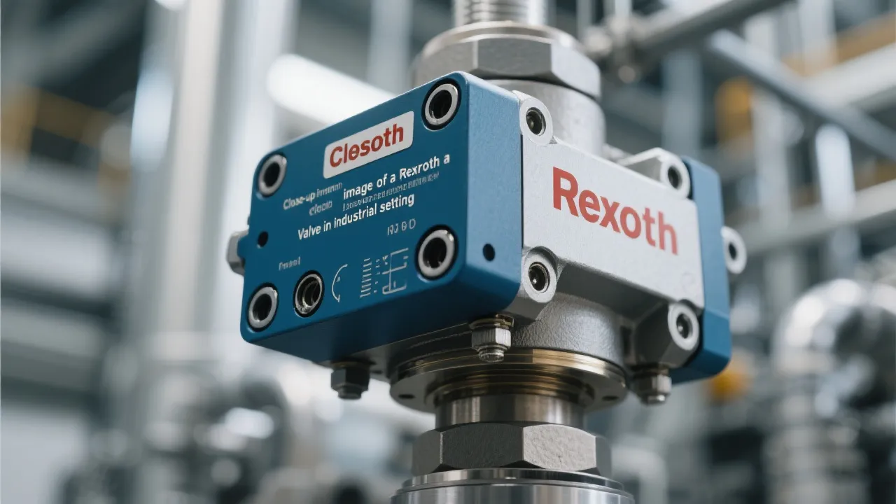
Understanding Rexroth Valve Systems
Rexroth Valves are quintessential components in various industrial applications, known for their precision and reliability. These hydraulic, pneumatic, and electrohydraulic valves regulate fluid flow in machinery, ensuring optimal performance and safety. Understanding their functionality and benefits is crucial for industries seeking efficiency and sustainability in their operations.

Unveiling Thermo Fisher Chromatography
This article explores the pivotal role of Thermo Fisher Chromatography in modern analytical science. Chromatography is crucial for separating compounds within mixtures, making it indispensable in industries such as pharmaceuticals and environmental testing. Thermo Fisher Scientific stands out in this field for its innovative solutions, leading to improved accuracy and efficiency in research and development.

Understanding Corrosion Inhibitor Manufacturers
In today's industrial landscape, corrosion inhibitor manufacturers play a crucial role in safeguarding equipment and infrastructure against corrosive damage. These manufacturers provide specialized chemicals that prevent corrosion in various environments, including industries such as oil and gas, marine, and construction. Understanding their operations and offerings is essential for selecting the right supplier and maintaining asset longevity.
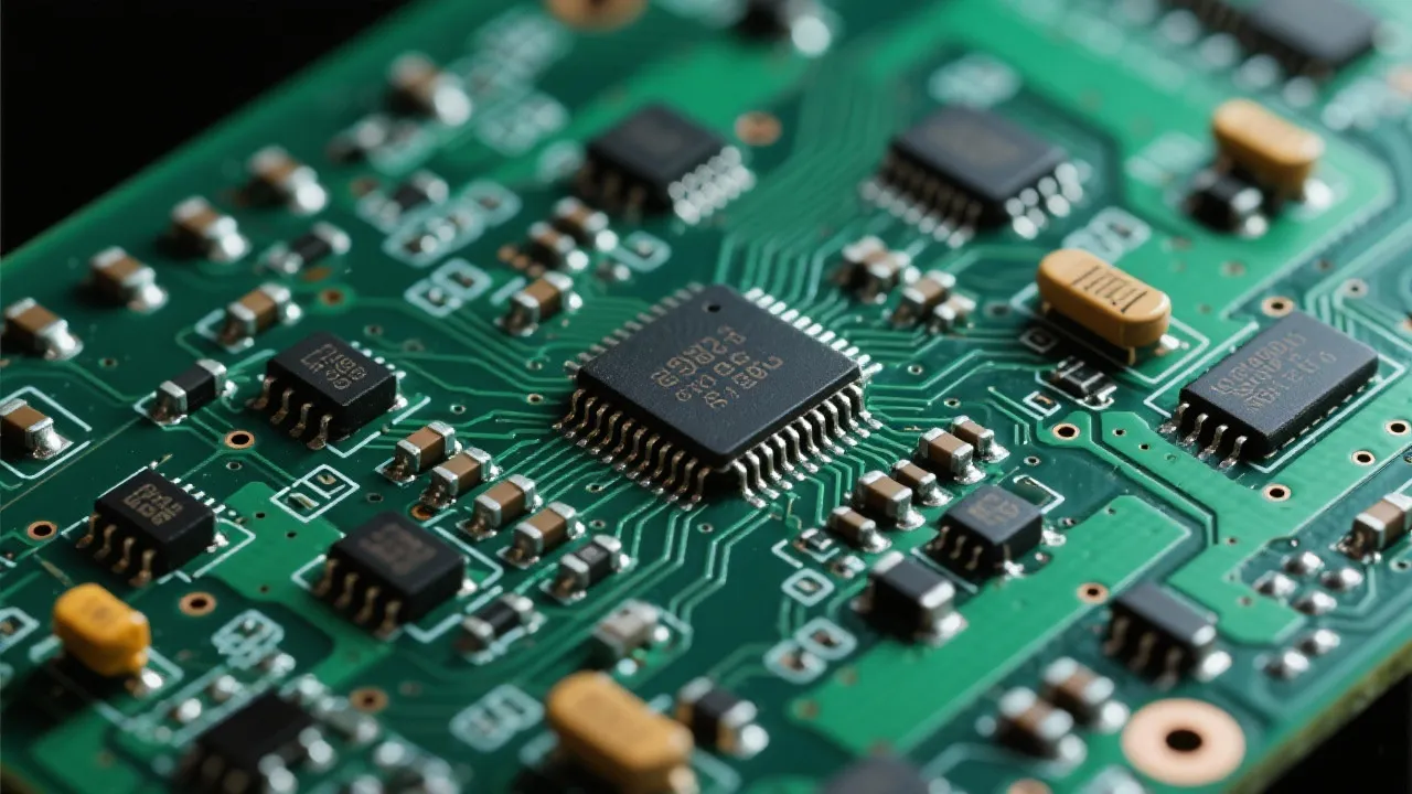
Analyzing Lm66100 Digikey Components
This article offers an in-depth analysis of the Lm66100 component available through Digikey, a renowned distributor of electronic components. The Lm66100, a load switch, is integral in industry applications, providing efficient power management. This piece explores its features, applications, and availability through Digikey, while offering a comprehensive guide for industry professionals seeking to optimize their electronic designs.

Leading Corrosion Inhibitor Suppliers
Corrosion inhibitor manufacturers play a crucial role in protecting materials from degradation. These companies specialize in creating chemical compounds that slow down or prevent the corrosive effects on various surfaces, especially metals. Understanding their production processes and solutions offered is vital for industries reliant on metal infrastructure.