This guide explains how the Extech EX900 can support electrical testing, troubleshooting, and temperature checks when used within its rated limits. The instrument is an industrial digital multimeter associated with functions such as voltage, current, resistance, continuity, frequency, capacitance, and infrared temperature measurement, depending on configuration and documentation. Its usefulness depends on correct lead placement, category ratings, environmental conditions, calibration status, and safe measurement procedures rather than on the number of available functions alone.
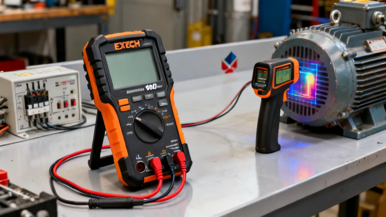
The Extech EX900 is designed for technicians who need more than a basic voltage tester. It combines the functions of a digital multimeter with non-contact infrared temperature measurement, giving users a practical way to investigate electrical and thermal conditions during maintenance work. That combination can be useful when examining control cabinets, motors, power supplies, heating equipment, batteries, and other systems where both electrical values and surface temperature matter.
Its value is best understood through the type of work it supports. An electrician may use the meter to verify voltage, check continuity, assess resistance, and measure current. A maintenance technician may use the infrared function to compare the temperature of bearings, terminals, circuit breakers, or motor housings. A service engineer may use the display, range selection, and recording functions to establish whether a reading is stable or changing over time.
However, the Extech EX900 should not be treated as a substitute for safe isolation procedures, a properly rated proving unit, a thermal camera, or a laboratory-grade measurement system. A multimeter provides a measurement under specific conditions. The quality of that measurement depends on the instrument, the test leads, the circuit, the environment, and the person carrying out the work.
From an industry perspective, the most important question is not whether the Extech EX900 has a long feature list. The more useful questions are whether its measurement categories match the installation, whether the expected values fall within its ranges, whether the instrument is maintained correctly, and whether the user understands the limitations of infrared and electrical testing.
Product specifications can change between revisions, regions, and package configurations. For that reason, the current Extech manual, product page, and markings on the individual instrument should always be treated as the final authority for ratings, ranges, included accessories, and safety instructions.
The Extech EX900 is commonly presented as an industrial multimeter with True RMS capability and an integrated infrared thermometer. Product documentation and supplier descriptions should be checked for the exact revision, included accessories, and currently specified ranges, because published details can vary between markets and production documentation.
In general, the instrument is intended to help users perform several classes of measurement:
The presence of these functions does not mean every function is suitable for every electrical environment. A current range designed for a limited input must not be connected across a voltage source. Likewise, a voltage range should not be used as a current path. Incorrect lead placement or function selection can create a short circuit, damage the meter, and expose the operator to hazardous energy.
True RMS measurement is particularly relevant in modern electrical systems. Many loads are not purely resistive and do not produce smooth sine waves. Variable-frequency drives, switch-mode power supplies, LED drivers, computers, battery chargers, and other electronic equipment can create waveforms that differ substantially from an ideal sine wave. A properly specified True RMS meter can provide a more meaningful AC reading than an average-responding meter when the waveform and frequency fall within the instrument’s stated performance range.
Even so, True RMS does not remove every limitation. Crest factor, bandwidth, conductor arrangement, waveform distortion, and the meter’s own accuracy specification still matter. The reading should be interpreted in the context of the system being tested.
The EX900 is therefore best regarded as a general-purpose field instrument. It can support fault-finding and condition assessment, but it does not automatically provide the specialized capabilities of an insulation resistance tester, power-quality analyzer, oscilloscope, clamp meter, or thermal imaging camera. Good maintenance practice depends on matching each task to the right tool.
Voltage measurement is one of the most common uses of the Extech EX900. DC voltage testing may be relevant to batteries, control circuits, photovoltaic equipment, electronic assemblies, and vehicle systems. AC voltage testing is commonly associated with mains circuits, motor supplies, building services, and industrial distribution equipment.
Before connecting the probes, the user should identify the circuit type, estimate the expected voltage, choose a suitable range, and confirm that the leads are inserted into the correct terminals. The black lead is normally connected to the common terminal, while the red lead is placed in the voltage terminal for voltage testing. The rotary selector or function buttons should be set to the required voltage mode before contact is made.
Measurements across a source are made in parallel. The probes should make firm contact with the intended points without allowing the metal tips to touch each other or adjacent conductors. On crowded panels, probe accessories with insulated tips or suitable test clips can help reduce the possibility of accidental contact.
When working on hazardous installations, a voltage reading alone does not prove that a circuit is safe. If a system is to be isolated, the correct procedure normally includes identifying the source, disconnecting it, securing the isolation, testing the test instrument on a known source, testing the circuit, and rechecking the instrument on the known source. The exact procedure must follow local regulations, workplace rules, and the requirements of the equipment owner.
DC polarity also matters. Reversed probes will usually produce a negative display rather than a positive one, but the user should still confirm the reference point and polarity before interpreting the result. In control circuits, an apparently low voltage can be caused by a poor reference connection, an open return conductor, a loaded supply, or a control output that is not intended to supply significant current.
Current measurement requires a different connection method. The meter is placed in series with the circuit so that the current flows through the instrument’s current input. This is fundamentally different from voltage measurement. Connecting a current input directly across a voltage source can create a low-resistance path and may cause an arc, fuse operation, instrument damage, or injury.
The Extech EX900 may be useful for checking operating current in selected circuits, provided that the expected current is below the applicable input rating and the correct fuse and terminal are used. The user should begin with the highest appropriate current range where uncertainty exists, then move to a lower range only when it is safe to do so.
Current measurement can interrupt a circuit, which makes it less convenient than a clamp meter for many industrial tasks. If the circuit must remain closed, a suitably rated clamp meter may be a better tool. The Extech EX900 should therefore be selected according to the access conditions and the measurement objective, not simply because it includes a current function.
After completing a current measurement, the lead should be returned to the voltage terminal before any subsequent voltage test. This simple habit prevents one of the most common multimeter accidents: leaving the red lead in a current jack and then placing the probes across a supply.
Current readings should also be associated with operating conditions. A motor may draw a high inrush current during starting and a lower value at steady state. A heater may cycle on and off, while a power supply may draw distorted current pulses. A single displayed number without information about timing, load, and system state may not be enough to identify a fault.
Resistance testing is generally performed on de-energized circuits. Stored energy in capacitors, batteries, motor drives, or other equipment can affect the reading and can damage the instrument. Power should be removed, and the circuit should be verified as de-energized before resistance or continuity testing begins.
Continuity mode is useful for identifying low-resistance paths, checking fuses, tracing conductors, and confirming switch operation. The audible signal is a convenience rather than a precise resistance result. A continuity tone indicates that the measured resistance falls within the meter’s programmed threshold; it does not prove that a connection is suitable for its intended load.
For example, a loose or oxidized connection may show continuity under a low test current but fail when the circuit carries operating current. Where voltage drop or contact quality is suspected, a voltage-drop test under load may be more informative than a simple continuity check.
Lead resistance can influence very low resistance measurements. Before testing a small resistance, the user may touch the probe tips together and observe the residual reading. This value represents the resistance of the leads and contact points and should be considered when interpreting a low result. For precision low-resistance work, a dedicated four-wire instrument may be more suitable.
Diode mode applies a small test stimulus and displays the forward voltage observed by the meter. It can help technicians distinguish between a conducting junction, an open device, and a shorted device. The component should normally be isolated from parallel circuit paths for a dependable result.
Complex electronic assemblies can produce misleading readings because transistors, protection devices, capacitors, and integrated circuits may be connected around the component under test. When a diode reading appears inconsistent with the design, the component should be tested according to the manufacturer’s service documentation.
Some power semiconductor assemblies include multiple junctions, internal resistors, suppression components, or gate structures. A normal diode-mode reading does not necessarily confirm that the device will operate correctly under voltage, current, temperature, and switching conditions. It is one diagnostic step rather than a complete functional test.
Capacitance measurement can assist with the assessment of selected capacitors, timing components, and electronic assemblies. The capacitor must be disconnected from the circuit and discharged safely before the measurement. A capacitor can retain dangerous energy even after equipment has been switched off.
A capacitance result should not be interpreted as a complete assessment of a capacitor. Equivalent series resistance, leakage current, operating temperature, voltage rating, and behavior under load may also be important. In motor and power applications, a capacitance value that appears close to its nominal rating does not necessarily prove that the component is healthy.
Large capacitors should be discharged using an approved method rather than by shorting the terminals with a screwdriver. Shorting can produce a damaging arc, weld the tool to the terminal, or damage the capacitor. The service documentation for the equipment should identify any controlled discharge requirements.
Frequency measurement can be useful in control systems, generator checks, inverter outputs, and electronic circuits. Duty-cycle measurement can provide additional information about pulse-width-modulated signals. These functions are meaningful only when the signal amplitude, frequency, waveform, and connection method fall within the meter’s specifications.
When testing outputs from variable-speed drives or other power-electronic equipment, the technician should consult the drive and meter documentation. High-frequency common-mode voltages, fast switching edges, and non-sinusoidal waveforms can create readings that require careful interpretation.
A frequency reading can confirm that a signal is present, but it may not show whether the signal has the correct shape, noise level, amplitude, phase relationship, or timing. If a control system is malfunctioning despite a seemingly correct frequency, an oscilloscope or manufacturer-specific diagnostic tool may be necessary.
Where the correct accessory is provided or separately approved, contact temperature measurement can be useful for surfaces that are small, low-emissivity, or difficult to assess accurately with infrared sensing. The probe must be suitable for the expected temperature range and must not be placed where it could become energized or interfere with moving equipment.
Contact probes require time to reach thermal equilibrium. A quick touch may produce a reading influenced by the probe’s previous temperature rather than the target. The user should allow sufficient stabilization time and should consider whether the probe is measuring the surface, air, fluid, or another part of the system.
The integrated infrared function is one of the most distinctive features associated with the Extech EX900. It allows the user to estimate the surface temperature of an object without placing a probe directly on it. This can make preliminary inspections faster, particularly where a surface is moving, difficult to reach, electrically energized, or too hot for direct contact.
Infrared measurement detects thermal radiation emitted by the target. The meter converts that radiation into a temperature estimate based on assumptions about emissivity, distance, and the field of view. The reading is therefore a surface measurement, not a direct measurement of the internal temperature of the object.
Emissivity is especially important. Dark, matte, non-metallic surfaces generally emit infrared energy more predictably than shiny or polished metals. Reflective surfaces can reflect radiation from nearby hot or cold objects, causing the displayed temperature to differ from the actual surface temperature. Painted metal, oxidized metal, rubber, plastics, and electrical insulation may produce more useful readings than polished copper or stainless steel.
A practical approach is to place a piece of matte black electrical tape or a suitable high-emissivity target on a safe, accessible area and allow it to reach the same temperature as the surface. The user can then measure the tape rather than the reflective metal. This method must be appropriate for the environment and should not compromise insulation, equipment operation, or safety procedures.
Every infrared instrument has a distance-to-spot relationship. The area measured becomes larger as the instrument moves farther away. If the target is smaller than the measurement spot, the result may include the surrounding surface and may not represent the target itself.
For a dependable inspection, the user should move close enough for the target to fill the measurement area while maintaining a safe working distance. This is particularly important when measuring a terminal, fuse body, bearing housing, or small electronic component. A reading taken from too far away may conceal a localized hot spot.
The infrared function is well suited to comparative inspection. For instance, the technician may compare similar phases, terminals, bearings, or circuit breakers operating under similar loads. A significant difference between otherwise similar components can justify further investigation. The comparison should account for load, airflow, ambient temperature, surface finish, and position.
Repeated measurements should be made from a similar distance and angle. Changing the angle can alter reflections from shiny materials, while changing the distance can alter the proportion of target and background within the measurement spot. Recording the measurement method makes future readings more useful for trend analysis.
Infrared measurement cannot see through glass, transparent plastic, dust, steam, or many other obstructions in the way people often expect. It measures the outer surface of the obstruction. In an electrical cabinet, a closed door may have a different temperature from the terminal inside, so the door temperature should not be treated as an internal component temperature.
Air movement can also affect results. Ventilation may cool one side of a motor or enclosure. Direct sunlight can heat surfaces and alter readings. Reflections from hot machinery, lamps, or nearby equipment can affect shiny targets. These issues do not make the function unusable; they mean that the inspection method must be controlled and the reading must be interpreted rather than accepted without question.
Infrared results should be treated as indications of thermal behavior. If a reading suggests a dangerous hot spot, the user should not rely on the handheld result alone before making a critical decision. Load measurements, contact temperature checks, thermal imaging, visual inspection, and manufacturer limits may all be needed to establish the cause and severity of the condition.
Traditional average-responding meters are typically calibrated to display the correct RMS value for a sinusoidal waveform. Their accuracy can decline when the waveform is distorted. Industrial and commercial systems increasingly contain loads that draw current in pulses or otherwise modify the waveform.
A True RMS meter measures the heating-equivalent value of an AC waveform within its specified bandwidth and crest-factor limits. This can improve the usefulness of measurements taken on systems containing rectifiers, drives, electronic lighting, power supplies, and other nonlinear loads.
There are still several points to consider:
An industry technician should record not only the displayed value but also the operating condition. Motor current measured during startup, acceleration, steady operation, and overload can differ substantially. A voltage measured at the source may not match the voltage measured at the load because of conductor impedance or connection problems.
True RMS is especially useful when comparing phases or loads that are expected to be similar. However, balance should not be judged from current magnitude alone. Phase angle, harmonics, supply impedance, motor loading, and drive configuration can all influence the result. If a reading is used to make an important maintenance decision, it should be compared with design data and historical measurements.
Measurement category ratings are central to selecting a multimeter. The ratings describe the type of electrical environment in which the instrument is intended to be used and the transient energy it is designed to withstand under specified conditions. Common categories include CAT II, CAT III, and CAT IV, with higher categories generally associated with locations closer to the electrical source and with greater potential transient energy.
Users should verify the exact category marking on the Extech EX900 itself, the test leads, and any accessories. The rating of the complete measurement setup is limited by its lowest-rated component. A meter with a suitable category marking cannot make an incorrectly rated lead safe.
Other essential precautions include:
The meter’s safety features should support a safe process, not replace it. In professional environments, electrical work should be carried out by competent personnel who understand the applicable codes, standards, and employer requirements.
Special caution is required around arc-flash hazards. A meter can be correctly rated and still be used in an unsafe manner if the operator reaches into an unsuitable enclosure, uses damaged accessories, stands in the wrong position, or works without the required assessment and protective equipment. The safest measurement is often the one that can be performed after the equipment has been isolated.
Write down what needs to be known. The question may be whether a supply is present, whether a fuse is intact, whether two phases are balanced, whether a motor housing is overheating, or whether a sensor signal has the expected frequency. A clear question helps determine the correct function and connection method.
Identify the system voltage, available fault energy, enclosure condition, temperature, moisture, access restrictions, and possibility of moving parts. Consider whether infrared measurement is appropriate or whether a contact probe, thermal camera, clamp meter, insulation tester, or another instrument is more suitable.
Check the Extech EX900 for visible damage. Confirm that the display, battery compartment, selector, terminals, and accessories are in good condition. If the meter has been dropped, exposed to excessive moisture, contaminated, or subjected to an overload, it should be evaluated before being returned to service.
Select the intended function and connect the leads to the correct terminals. For voltage, resistance, continuity, diode, frequency, and capacitance measurements, the voltage terminal is normally used with the common terminal. Current measurement generally requires a dedicated current terminal. The markings on the instrument take priority over general descriptions.
Before testing a potentially energized circuit, check the instrument on a known live source or an approved proving device. After the test, repeat the check. This process helps identify a depleted battery, damaged lead, blown fuse, or internal failure that could otherwise create a false assumption of safety.
Make contact carefully and maintain stable probe placement. Avoid stretching across the equipment or allowing the leads to rest on sharp edges, hot surfaces, or moving mechanisms. Observe whether the reading is stable, fluctuating, unexpectedly high, or outside the expected range.
Compare the result with the equipment manual, design information, maintenance history, and measurements from related points. Repeat the test using a different method where the consequence of an incorrect decision is significant. For temperature inspections, compare equivalent targets and consider load and environmental conditions.
Document the date, instrument identification, function, range, test location, operating load, ambient conditions, result, and any unusual observations. A measurement without context is difficult to reproduce and may be misinterpreted during a later maintenance review.
After testing, remove the probes in a controlled manner, return the equipment to its intended configuration, reinstall covers where required, and return the meter leads to a safe terminal arrangement. If the circuit was interrupted, confirm that all connections, fuses, and protective devices have been restored before returning the equipment to service.
The Extech EX900 can assist with initial checks on motor supply voltage, phase-to-phase conditions where applicable, winding resistance comparisons on isolated equipment, and surface-temperature comparisons. Infrared checks may identify a warmer bearing housing, terminal connection, or motor casing.
Temperature differences are clues, not diagnoses. A warmer component may reflect higher load, poor lubrication, misalignment, restricted airflow, bearing wear, or an electrical imbalance. The technician should combine the reading with vibration data, current measurements, operating history, and the motor manufacturer’s limits.
When comparing motor phases, the measurements should be taken under similar load and at similar points in the operating cycle. An imbalance may originate in the supply, motor windings, cable connections, or mechanical load. Resistance checks performed when the motor is cold may not directly represent winding behavior at operating temperature.
During a planned inspection, the infrared function may help identify components that are warmer than comparable components under similar load. The user should maintain the required approach boundaries and follow the site’s arc-flash and energized-work policies.
When a hot connection is suspected, the next steps may include verifying torque according to the equipment manufacturer’s instructions, checking conductor condition, assessing load balance, and inspecting for oxidation or mechanical damage after the circuit has been safely isolated. Tightening a connection without understanding the cause may not resolve the problem.
A warm fuse, breaker, or terminal may be normal if it is carrying a high load, but an abnormal temperature difference between equivalent devices deserves attention. The inspection should account for enclosure ventilation, component age, conductor size, phase loading, and the thermal behavior of neighboring components.
Voltage, resistance, continuity, and temperature measurements can support troubleshooting of heaters, fans, contactors, thermostats, and control circuits. Infrared readings may help compare supply and return temperatures or locate an area with abnormal heat transfer.
The displayed temperature should be considered alongside airflow, sensor position, insulation, and system control settings. A surface temperature does not necessarily equal the temperature of the air or fluid inside the equipment.
For heating elements, a resistance reading can help identify an open element or a grossly abnormal value, but it may not reveal a fault that appears only when the element becomes hot. Similarly, a fan motor may show a normal static resistance while drawing excessive current because of mechanical restriction or bearing damage.
Frequency, duty cycle, DC voltage, resistance, and diode functions can support checks on sensors and control boards. Electronic equipment is sensitive to incorrect connections and electrostatic discharge. The technician should follow the equipment service manual and use appropriate grounding and probing practices.
Some circuits may require a high-impedance instrument, differential measurement, or an oscilloscope. If the signal is fast, floating, or connected to a switching power stage, the Extech EX900 may not provide the complete information needed for diagnosis.
When working on control boards, the user should avoid allowing probe tips to slip between closely spaced pins. Insulated probe accessories, clip leads, and an appropriate lighting arrangement can reduce the risk of bridging adjacent conductors. The circuit’s reference point should be identified from the schematic rather than assumed from physical position.
DC voltage checks can help assess battery strings, control supplies, and charging systems. A voltage reading alone does not establish battery capacity or internal condition. Load testing, conductance testing, electrolyte assessment, or manufacturer-specific diagnostics may be required depending on the battery technology.
When testing large battery systems, the available short-circuit current can be substantial even at relatively modest nominal voltage. Tools, leads, protective equipment, and procedures must be selected accordingly.
In a series-connected battery string, an individual unit with an unusual voltage may indicate imbalance, poor connection, charging problems, or a failing cell. Measurements should be recorded consistently and interpreted alongside battery age, temperature, charging voltage, and load history.
DC voltage and continuity functions may assist with preliminary checks on vehicle power systems, relays, fuses, sensors, and charging circuits. The technician should verify that the selected function and input range are appropriate for the vehicle system and that inductive transients will not exceed the meter’s limits.
Temperature comparisons may help identify an overheating connector, alternator housing, battery terminal, or brake component during a controlled inspection. Infrared readings on reflective metal should be treated cautiously, and the instrument must never be used in a way that places the operator near moving belts, fans, wheels, or other hazards.
Resolution refers to the smallest displayed increment, while accuracy describes how close the reading is expected to be to the actual value under specified conditions. A display with many digits does not automatically provide high accuracy. The relevant specification normally includes a percentage of reading plus a number of counts, along with conditions such as temperature, humidity, and frequency.
For professional use, the Extech EX900 should be calibrated or verified at intervals appropriate to its workload and risk. A meter used occasionally in low-risk maintenance may follow a different schedule from one used daily in industrial troubleshooting. The interval should be based on the manufacturer’s guidance, internal quality procedures, previous verification results, and the consequences of measurement error.
Calibration is not the same as repair. If an instrument fails verification, the cause should be investigated. Possible causes include damaged leads, a weak battery, contamination, mechanical impact, environmental exposure, or an internal fault.
Users should allow the meter and the target to reach appropriate environmental conditions where practical. Extreme temperature, condensation, dust, and electromagnetic interference can affect instruments and measurements. The operating and storage limits in the official documentation should be consulted before using the meter in demanding environments.
Verification can include checking the meter against a known reference, a calibrated source, or another instrument whose accuracy is suitable for the comparison. A reference check should not be confused with a complete calibration, but it can reveal a sudden change in performance between formal calibration intervals.
Routine care contributes directly to measurement reliability. The Extech EX900 should be kept clean and dry, with the selector returned to an appropriate position after use. Test leads should be coiled without sharp bends and stored where the insulation will not be crushed or contaminated.
Before opening a battery compartment or replacing a fuse, disconnect the test leads and ensure that the instrument is not connected to a circuit. Use the replacement type specified by the manufacturer. Improvised fuses or incorrect batteries can compromise both operation and safety.
If the meter will not be used for an extended period, storage conditions should follow the product documentation. Batteries may need to be removed where leakage could damage the instrument. After storage, inspect the meter and verify its operation before relying on it for important work.
The infrared sensor area should be protected from dirt, fingerprints, oil, and scratches. Contamination on the optical window can affect the amount of radiation reaching the sensor and may produce inaccurate temperature results. Cleaning should be performed according to the manufacturer’s instructions rather than with abrasive materials or aggressive solvents.
A purchasing decision should begin with the required measurements and electrical environment. Buyers should verify the following points with the manufacturer’s current documentation or an authorized supplier:
Price information was not provided for this article, and the cost of an Extech EX900 can vary according to region, supplier, taxes, shipping, warranty coverage, and package contents. A lower listed price may not represent the better purchase if it excludes suitable leads, carries uncertain warranty terms, or comes from a source that cannot verify product authenticity. Buyers should compare the complete delivered package and documentation rather than the headline price alone.
Supplier selection is also relevant. A reputable supplier should be able to identify the model clearly, describe the included accessories, provide applicable warranty information, and answer questions about calibration and returns. For organizations using measurement equipment in a quality-controlled process, traceable calibration documentation may be more important than a modest difference in purchase price.
Organizations should also consider total ownership cost. Replacement leads, protective cases, batteries, calibration, technician training, downtime, and service support can all influence the long-term value of an instrument. A meter that is inexpensive to purchase but difficult to maintain may be less economical over several years.
| Instrument type | Primary strength | Typical limitation | When it may be preferred |
|---|---|---|---|
| Extech EX900 industrial multimeter | Combines electrical measurements with infrared temperature inspection in one handheld instrument. | Infrared readings depend on emissivity, target size, distance, and surface conditions; current measurement may require circuit interruption. | General electrical troubleshooting and preliminary thermal comparisons. |
| Basic digital multimeter | Simple voltage, resistance, and continuity testing with straightforward operation. | May lack True RMS capability, infrared temperature measurement, advanced recording functions, or broader ranges. | Routine low-complexity maintenance within the instrument’s category rating. |
| Clamp meter | Measures current around a conductor without opening the circuit. | May have less comprehensive resistance, capacitance, or low-level electronic measurement capability. | Motor, HVAC, distribution, and load-current checks where circuit interruption is undesirable. |
| Thermal camera | Displays a broader thermal image and can show temperature patterns across equipment. | Usually costs more and still requires attention to emissivity, reflections, focus, and measurement range. | Detailed thermal surveys, pattern recognition, and documentation of larger areas. |
| Insulation resistance tester | Applies a defined test voltage to assess insulation resistance. | Not a general-purpose multimeter and may not be suitable for connected electronic equipment. | Motor, cable, and insulation diagnostics performed under a controlled procedure. |
| Oscilloscope | Shows waveform shape, transients, timing, and signal behavior. | Requires greater technical knowledge and appropriate probes and safety methods. | Power electronics, control signals, communications, and dynamic fault analysis. |
Reliable use of the Extech EX900 depends on several conditions. The instrument must be within its calibration or verification period, the battery must support normal operation, and the leads must be undamaged and suitable for the environment. The measured signal must fall within the relevant function’s range, frequency, crest-factor, and input limitations.
The test location should be assessed for moisture, dust, conductive contamination, heat, vibration, electromagnetic fields, and restricted access. If the instrument will be used in a hazardous location, the user must verify whether the meter is approved for that specific atmosphere. A general industrial label does not automatically indicate suitability for explosive or specially classified areas.
For infrared measurements, the target should be large enough to fill the measurement spot, and the surface should have appropriate emissivity or be prepared with a suitable high-emissivity reference. Reflections, direct sunlight, airflow, and obstructions should be considered. The user should record the distance, angle, approximate load, ambient temperature, and target condition when the result may be used for maintenance decisions.
For energized electrical measurements, the operator must have the necessary competence and authorization. The instrument’s category rating, lead rating, personal protective equipment, approach distance, and site procedure must all be appropriate. Where the risk assessment does not support energized testing, the circuit should be isolated and verified using the approved process.
Environmental conditions can affect both electrical and temperature measurements. Condensation can create leakage paths, low temperatures can alter battery performance, and strong electromagnetic fields can cause unstable or unexpected displays. If a result changes dramatically when the leads are repositioned or the instrument is moved away from a source of interference, the measurement setup should be investigated.
The most reliable technical source is the current Extech product page and user manual for the exact EX900 model. These documents should be used to confirm electrical ranges, accuracy, category ratings, environmental limits, battery requirements, fuse types, infrared specifications, and operating instructions.
Users should also consult the relevant electrical safety requirements applicable in their jurisdiction and workplace. International standards for measurement equipment, national wiring rules, employer procedures, and equipment manufacturer instructions may impose requirements that are not visible in a short product description.
Supplier listings are useful for checking availability, package contents, and commercial terms, but they should not replace the manufacturer’s manual for safety-critical technical decisions. If two listings provide different specifications, the model marking and current manufacturer documentation should take precedence.
Documentation should be available to the people who use the meter, not only to the purchasing department. A short site procedure can identify approved functions, prohibited uses, inspection requirements, calibration intervals, and actions to take when a meter is damaged or fails a check.
This is one of the most serious operating errors. The current input is designed to be part of a circuit path, not to be placed directly across a voltage source. Users should develop the habit of checking lead position before every voltage measurement.
Resistance mode sends a test signal into the circuit. External voltage can distort the result or damage the meter. Isolate and verify the circuit before selecting resistance, continuity, diode, or capacitance functions.
A shiny metal terminal, a distant small component, or a surface exposed to strong reflections may produce a misleading result. Move closer where safe, use a suitable reference surface, and compare similar targets under similar operating conditions.
A changing final digit does not necessarily indicate a fault, and a stable display does not guarantee accuracy. Consult the specification and consider whether the uncertainty is significant for the decision being made.
Current, temperature, voltage, and frequency depend on system load and operating state. A reading taken during startup cannot be compared directly with a steady-state reading without understanding the difference.
The fuse is part of the meter’s safety system. A substitute with the wrong interrupt rating, speed, or current rating can leave the instrument inadequately protected during an overload.
A lead can be damaged internally even when the outer insulation does not show obvious marks. If the meter has experienced an overload, arc, or unexpected fault current, the leads and instrument should be inspected and verified before reuse.
A continuity tone only indicates that the resistance is below a programmed threshold. It does not demonstrate that a connection can carry its rated current, that insulation is intact, or that a protective conductor is correctly installed.
From an industrial measurement perspective, the Extech EX900 is attractive when a technician needs a versatile handheld instrument for routine electrical checks and an initial view of surface temperature. The integrated infrared function can reduce the need to change instruments during an inspection, while True RMS capability can support measurements on many contemporary electrical loads.
Its strongest role is as a diagnostic and screening tool. It can help identify whether a supply is present, whether a circuit path exists, whether a component has an unusual resistance, whether an AC waveform produces a meaningful RMS value, or whether one comparable surface is hotter than another. These observations can guide the next maintenance action.
It should not be selected solely on the assumption that a combined instrument performs every specialized task equally well. A clamp meter may be more efficient for repeated current checks, an insulation tester may be necessary for insulation assessment, and a thermal camera may reveal temperature patterns that a single-point infrared reading cannot show. Good instrument selection is task-specific.
The Extech EX900 is therefore best viewed as part of a measurement toolkit. Its effectiveness depends on competent operation, appropriate safety controls, sound interpretation, and documented maintenance practice.
For organizations, its value may be greatest when it is integrated into a repeatable inspection process. Technicians can use the meter for initial observations, compare results with baseline data, identify abnormal trends, and escalate complex findings to more specialized equipment. In this role, the instrument can support preventive maintenance without being expected to answer every diagnostic question by itself.
The Extech EX900 is used for a range of electrical measurements and, in the commonly described configuration, infrared surface-temperature inspection. Typical applications include voltage checks, current measurement within rated limits, resistance and continuity testing, frequency checks, capacitance or diode testing, and preliminary thermal comparisons on electrical and mechanical equipment.
It is commonly identified as a True RMS industrial multimeter. The exact operating conditions, frequency response, crest-factor limitations, and accuracy should be confirmed in the current manufacturer documentation for the instrument being purchased or used.
Its integrated infrared function is intended for non-contact surface-temperature measurement. The result is influenced by emissivity, target size, distance, reflections, airflow, and obstructions. It does not directly measure the internal temperature of an object.
It can measure a visible surface that is accessible to the infrared sensor, but it cannot see through a closed metal door or other opaque obstruction. If the panel must remain closed, the reading may represent the enclosure surface rather than the internal connection. Energized access must follow the site’s electrical safety procedure.
No. A single-point infrared meter and a thermal camera serve different purposes. The Extech EX900 can provide a quick temperature estimate at a selected target, while a thermal camera can show a broader heat pattern and support visual comparison across an area.
Conventional multimeter current measurement normally requires the meter to be inserted in series with the circuit. A clamp meter is generally more suitable when the circuit must remain closed. The user should never place a current input directly across a voltage source.
Resistance measurement should be performed on a de-energized circuit after appropriate isolation and verification. Stored energy must also be considered, particularly in capacitors, drives, battery systems, and power supplies.
First confirm the function, range, lead position, and instrument condition. Prove the meter on a known source, then repeat the test using a safe and appropriate method. Consider induced voltage, open neutrals, incorrect reference points, phase relationships, and the equipment schematic. Do not assume that an unexpected reading is harmless.
Confirm the exact model, current manufacturer specifications, measurement category, electrical ranges, infrared specifications, included accessories, warranty, calibration options, and supplier reliability. Also verify that the instrument suits the voltage environment and measurement types found in the intended workplace.
No specific price or supplier was supplied for this article. Current pricing should be confirmed with a reputable regional supplier or the manufacturer’s approved distribution network. Compare taxes, shipping, warranty coverage, calibration documentation, and package contents as well as the listed purchase price.
The interval should follow the manufacturer’s recommendations and the user’s quality and risk requirements. Frequency of use, measurement importance, environmental exposure, previous verification results, and whether the instrument has been overloaded should all be considered. A failed verification should trigger evaluation before further critical use.
True RMS can provide a more representative AC value when the waveform is distorted, provided that the signal remains within the meter’s specified frequency, crest-factor, and accuracy conditions. It does not guarantee correct results for every switching waveform or high-frequency signal.
A beginner may learn its functions under supervision, but safe use on energized industrial equipment requires appropriate training and authorization. Reading a display is not enough; the user must understand terminal selection, measurement category ratings, isolation procedures, lead safety, and the limitations of each function.
Remove it from critical service and inspect the housing, display, selector, terminals, leads, and battery compartment. A drop can affect internal safety barriers or calibration even when the exterior looks acceptable. The meter should be verified or professionally inspected before being trusted for hazardous measurements.
Possible causes include changing load, airflow, target angle, distance, reflections, emissivity differences, sensor contamination, or insufficient stabilization. Repeating the measurement from a consistent position and comparing a suitable high-emissivity target can help determine whether the variation is genuine or caused by the measurement method.
The Extech EX900 offers a practical combination of industrial multimeter functions and infrared surface-temperature inspection. Its True RMS capability may be useful when working with modern nonlinear loads, while its temperature function can support quick comparisons during electrical and mechanical maintenance.
The instrument should be chosen according to the required ranges, category rating, environment, and measurement method. Correct lead placement, safe isolation, calibration control, and careful interpretation are more important than the number of functions shown on the front panel. Infrared readings should be treated as surface observations, and specialized tasks should be assigned to specialized instruments when necessary.
For buyers, the most reliable process is to confirm the current technical documentation, compare complete package contents, evaluate supplier support, and select the Extech EX900 only when its capabilities match the intended work. Used within those conditions, it can serve as a useful component of a disciplined electrical troubleshooting and maintenance program.
The instrument’s greatest practical benefit is flexibility. A technician can move from checking a control voltage to examining resistance, reviewing current, or comparing surface temperature without carrying several separate basic tools. That flexibility is valuable, but it must be supported by sound measurement technique and an understanding of what the display can and cannot prove.
When used responsibly, documented properly, and supplemented with specialist equipment where required, the Extech EX900 can help maintenance teams identify abnormal conditions earlier, improve troubleshooting efficiency, and make better-informed decisions about inspection, repair, and further testing.
Striking the Perfect Balance: Navigating Premiums and Out-of-Pocket Expenses in Senior Insurance Plans

Explore the Tranquil Bliss of Idyllic Rural Retreats

How to Make Lasting Memories at Disneyland Attractions

Affordable Phones and Plans for Seniors

Affordable Full Mouth Dental Implants Near You

Unlock the Top Kept Secrets to Finding Your Ideal Dentist for Flawless Dental Implant Results!

Discovering Springdale Estates

Unveiling RS Sul Telecom Services

The Guide to Car Trading


Navigating Retirement Planning with Confidence
Approaching retirement brings a mix of excitement and concern. Finding the right retirement advisor is crucial for a secure and comfortable future. This guide offers practical advice on selecting an advisor, understanding their roles, and becoming financially astute yourself.
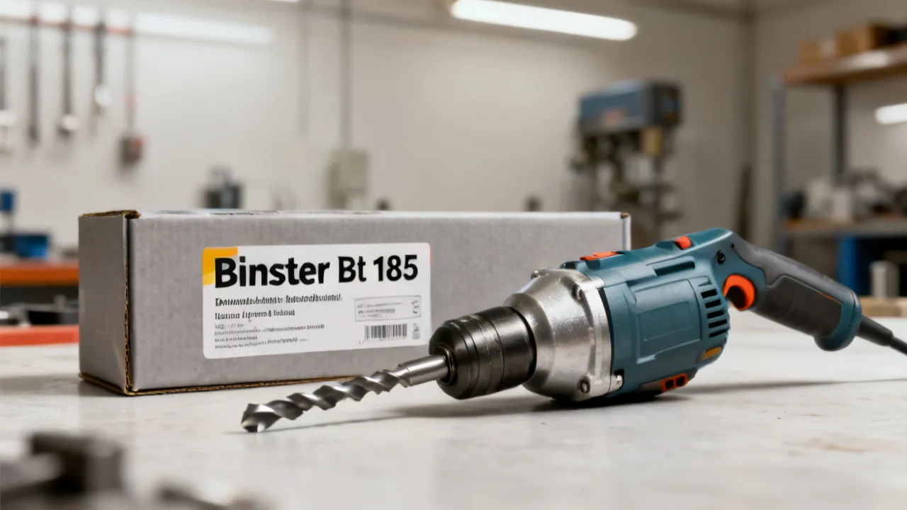
Binster Bt 185: Buyer’s Guide and Market Analysis
Binster Bt 185 is a specific industrial model people look up for procurement decisions, compatibility planning, and performance expectations. This guide explains, in an objective way, what buyers typically evaluate—specs, supplier reliability, documentation, and risk controls—so you can compare offerings and choose confidently based on verified information.

Posic Ebserh: How to Understand Your Options
Posic Ebserh helps people navigate healthcare-related planning and service access with clarity. This guide explains the core meaning and context behind the terms, then offers an objective framework for evaluating programs, responsibilities, and practical next steps. It also highlights what to prepare before contacting a supplier or healthcare coordinator, using neutral criteria and local sensitivities.

Using NotebookLM Effectively for Smarter Knowledge Work
This guide explains how NotebookLM can support structured note-taking and efficient knowledge work, from organizing sources to improving retrieval and writing workflows. Background context covers what NotebookLM is, why notebook-style systems matter, and how professionals commonly evaluate accuracy, privacy, and reliability when working with AI-assisted research tools.
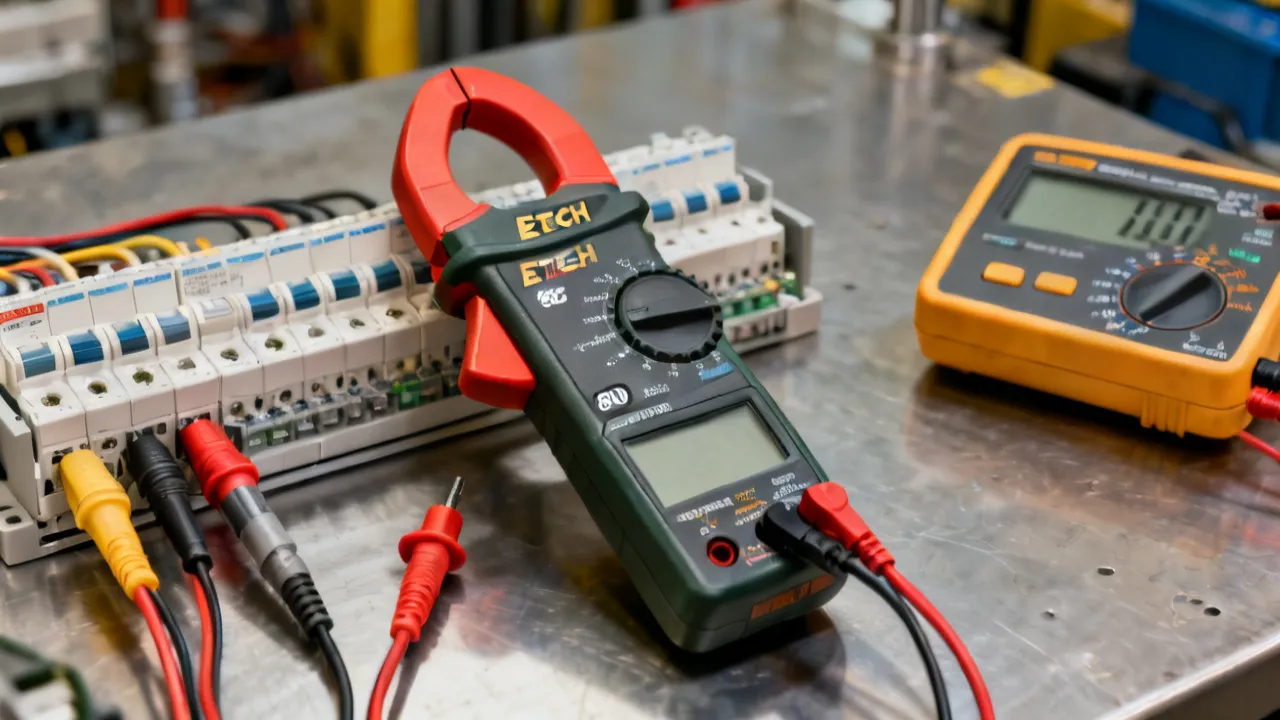
Extech EX800: A Practical Measurement Guide
This guide explains how to evaluate and use the Extech EX800 series of clamp meters for electrical troubleshooting, maintenance, and current measurement. The EX800 designation refers to a family of Extech instruments whose exact capabilities vary by model, so users should confirm the model number, measurement category, jaw rating, and manual before testing. The article covers operating principles, safety, accuracy, maintenance, selection criteria, and common questions.
Extech EX900: A Practical Measurement Guide
This guide explains how the Extech EX900 can support electrical testing, troubleshooting, and temperature checks when used within its rated limits. The instrument is an industrial digital multimeter associated with functions such as voltage, current, resistance, continuity, frequency, capacitance, and infrared temperature measurement, depending on configuration and documentation. Its usefulness depends on correct lead placement, category ratings, environmental conditions, calibration status, and safe measurement procedures rather than on the number of available functions alone.